


Biotechnological Leading Company
Lens
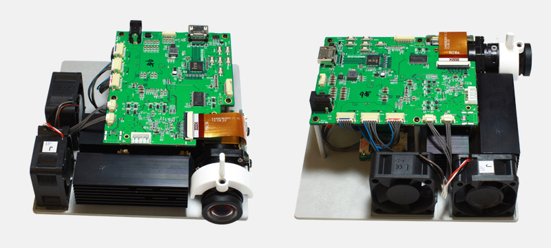
DODP30D EVM
DODP30D EVM Overview
The user’s guide provides an overview of the DODP30D EVM(Evaluation Module).
DODP30D EVM Block Diagram
- DMD : DLP3010 (0.3")
- Controller : DLPC3438
- PMIC/LED Driver : DLPA3000
- MCU : MSP430
- ITE HDMI Receiver : IT6801
- Audio : TLV320DAC
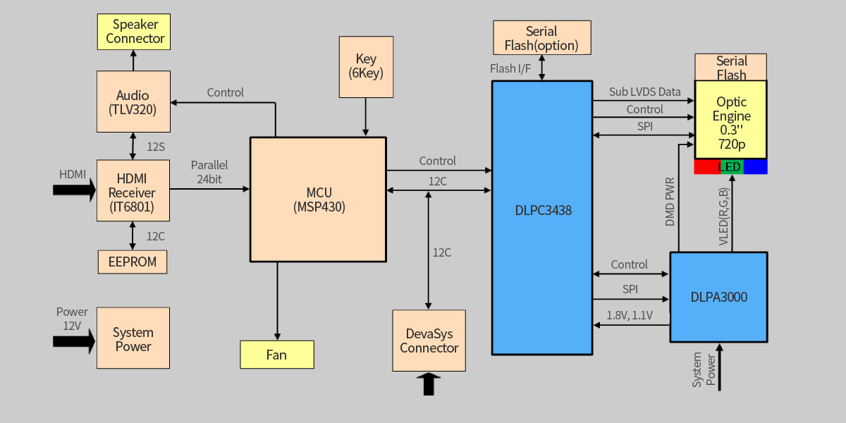
DODP30D EVM Block Diagram
-
Power up : DC 12V, 3A Adapter connector to the J8.
Adapter Power ON LED(LED11), MCU Power on LED(LED4) will turn on light that 12V Power is applied. - Press the power switch(S1), the DLP3438 and DLPA3000 is turn on. The PROJ_ON LED will turn on.
- EVM is turned on; Projector will default to display splash image.
- If needed connect a HDMI source to the EVM and communicate to the EVM over the GUI software.
HDMI input source is 1208 x 720(HD). - When turning off the projector, press the power switch(S1). Turn off the power switch(S1) prior to removing
power cable. Note: To avoid potential damage to the DMD it is recommended to turn off the projector with
the power switch(S1) before disconnecting the power. - LED Current is default 4.0A.
Table 1. LEDs on Stats
| LED | Name | Description |
|---|---|---|
| LED11 | SYS_5V | 12V Power applied, Regulated 5V power on |
| LED4 | P3P3V | Regulated 3.3V power on |
| LED9 | PROJ_ON | Projector is turned on |
| LED10 | RESETZ | Projector is Reset |
| LED2 | HOST_IRQ |
ON during DLPC3438 boot OFF when projector is D5 HOST_IRQ running. Indication of DLPC3438 boot-up completed and ready to receive commands |
| LED1 | Stats LED1 | ON When MSP430 operating |
| LED3 | Stats LED2 | ON When External HDMI mode |
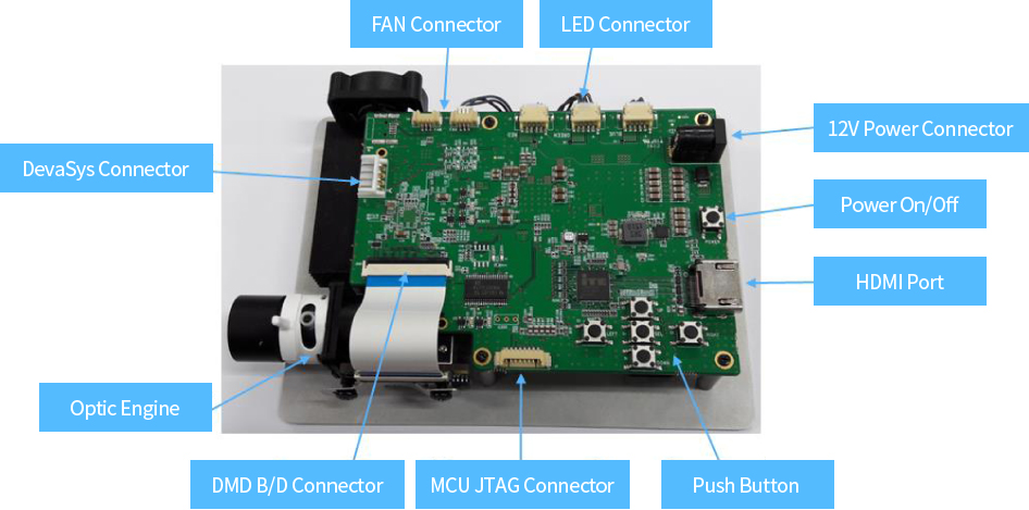
Table 2. Connector List
Connector
| LED | Description |
|---|---|
| J1, J2, J3 | Connector for Led Cable |
| J8 | 12V DC Jack |
| J104 | Connector for the HDMI |
| J10, J12 | Connector for Fan |
| J5, J7 | Connector for Audio Speaker |
| J15 | Connector for the I2C interface (DevaSys) |
| J6, J11 | Unsupported |
Table 2. Connector List
| LED | Description |
|---|---|
| J1, J2, J3 | Connector for Led Cable |
| J8 | 12V DC Jack |
| J104 | Connector for the HDMI |
| J10, J12 | Connector for Fan |
| J5, J7 | Connector for Audio Speaker |
| J15 | Connector for the I2C interface (DevaSys) |
| J6, J11 | Unsupported |
Table 3. Switch List
| Switch | Description |
|---|---|
| S1 (POWER) | Projector Power On/Off Switch |
| S3 (LEFT) | Change Led Current total 8 steps |
| S4 (SELET) |
Source Selection 1st Press : Splash image 2nd Press : Test pattern 3rd Press : Curtain Colors Pattern 4rd Press : HDMI input |
| S5 (RIGHT) | Splash, Test Pattern, Curtain image change. (Cycle Right direction) |
| S6 (DOWN) | Flip image N/S or E/W |